Tuesday, 2 October 2018

Test Coding

Test Coding - Weeks 7, 8 & 9 

After a busy few weeks of not being able to work on the project, I sat down and did some research on Arduino coding and the Tri-axial accelerometer. I found a lot of Arduino help but sorting through the stuff that was of no use to me and finding the few pieces of code I needed was the hard part. 
In our project we will be using the accelerometer as a sensor to detect deceleration in order for the Arduino to determine when to flash the brake lights. Therefore, the code I needed was to let the Arduino know what the signals being fed to it meant and to tell it to send power to a digital output when the signal is below a certain value. Below is what I came up with.
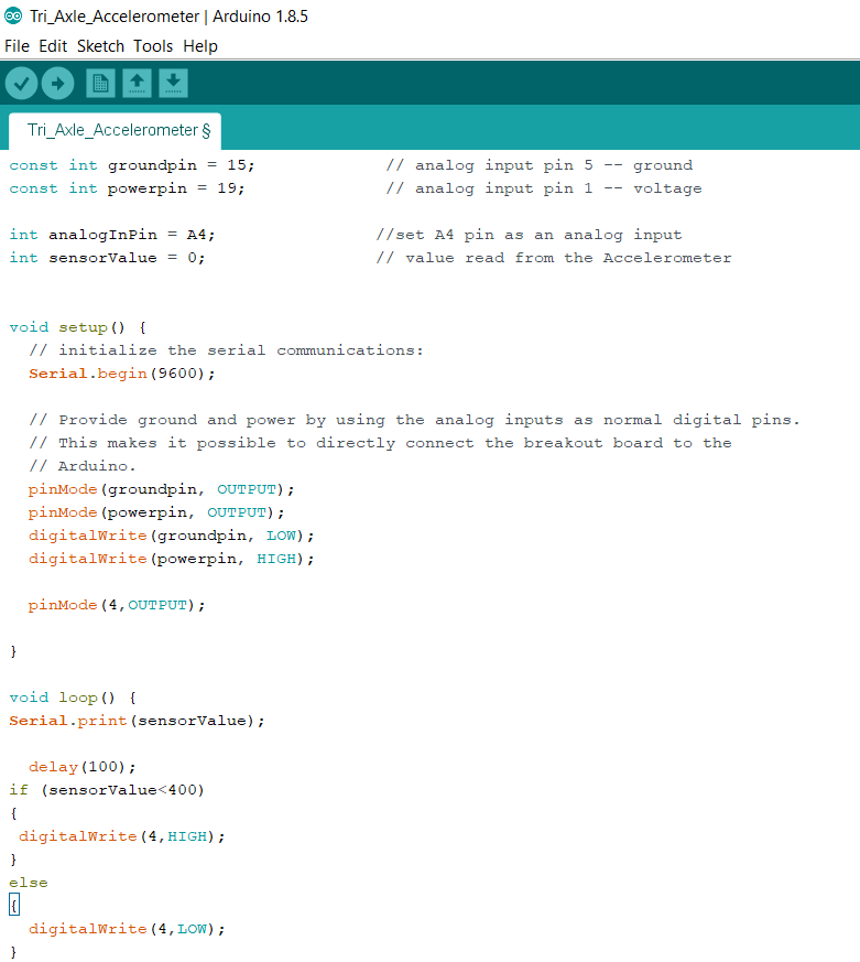


This sketch was purely to test the code and get a better understanding for it. The next step is to do some testing on the values given from the accelerometer chip and set up the full circuit with the transistor, relay, and the 4 LED's.


Thursday, 6 September 2018

Wiring and Components

Wiring and Components  - Week 5 & 6


After racking my brain trying to figure out how to wire the adaptive brake lights so that if the Arduino circuit fails, the brake lights will still work. I was toying with the idea of adding a resistor circuit which is activated by the Arduino and draws current from the lights to turn them off. However, there is a much simpler solution which uses a normally closed relay which will be switched into the off position to break the circuit. This will be done by the Arduino Uno and an NPN transistor. Below is a rough wiring diagram to display the idea.


The components we will be using are:

Sensor - 3-Axis accelerometer module for Arduino
Though we only require one axis for deceleration we will be using this sensor because its compatible with the Arduino and it is readily available.

Control Circuit - Arduino UNO, BD139 NPN transistor with a resistor added to the base to control voltage and a normally closed relay with a diode for protection.

Output Circuit - We will be using the existing brake light circuit which consists of the switch at the pedal and the lights.


Monday, 20 August 2018

Component Discussions

Component Discussions - Week 3 & 4


After doing our own research on components that could be used to activate the pulsing of the brake lights under heavy braking conditions, I talked to my lecturers about what they thought would be the best to use. We decided that a pitch sensor could work but not all cars have the same amount of dive under heavy braking conditions so the system would have to be calibrated for each vehicle it was put into. The pressure sensor could also be used but again, every vehicle is different and would require testing and calibration for each vehicle. Therefore, the sensor that was agreed upon was the Accelerometer which will sense the amount of deceleration the vehicle is experiencing and activate the pulsing when this deceleration is above a determined value. This value will be decided after additional research of emergency braking maneuvers. A good point that was brought up also, was that if the brake system is not operating as it should then a sensor should be in place to identify if the driver is applying a lot of force to try and decelerate quickly. This will pulse the brake lights and warn following drivers to slow down in the event of brake failure of the lead vehicle which would not produce the desired deceleration.   
Image result for accelerometer

Figure 1. Arduino 3-axis Accelerometer. (Jaycar, n.d.).

Reference: 
Jaycar. (n.d.). 3-axis Accelerometer. Retrieved from 


Wednesday, 8 August 2018

Initial Research

Initial Research - Week 1 & 2


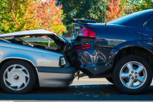
During the first couple of weeks I researched the issue of rear-end collisions and found that they are the most common type of collision. Though not usually fatal, they do end up costing drivers and insurance companies a lot of money. The main cause of these collisions is distracted driving. Weather it be using a cellphone, changing music, tired driving or distractions from passengers, it is evident that the conventional brake lights are not enough when emergency baking maneuvers are performed. The conventional brake lights also do not indicate the rate of deceleration of the vehicle making it sometimes hard to judge how hard you need to brake.

Image result for rear end collision
Figure 1. Rear End Collision. (Ellis Law Corporation, 2017)

After some more research I found that Mercedes Benz had a system to remedy this problem. A system that pulses the brake lights under heavy deceleration was incorporated. It was proven that this system decreased reaction time by 0.2 seconds and shortened stopping distances. By using a pulsing break light it grabs drivers attention more effectively than a conventional solid red light. Once the system is more widely used drivers will become more accustomed to the system and recognize the emergency braking maneuvers quicker and further decrease reaction times.

Figure 2. Adaptive Brake Light Technology. (QY Reports, 2018)


References:

Ellis Law Corporation. (2017). Rear End Collision. Retrieved from https://ellisinjurylaw.com/auto/car-accident/rear-end-collision/


Final System

Final System    Combining the previous steps together we came up with a final system that could sense the deceleration rate of a vehicl...